
| Progress Of The Tim Buehring Mi-Jack Translift Crane A little history on this Z scale Mi-Jack project: In July of 2004, with MTL announcing that they had plans to release a Gunderson Husky, I became interested in Intermodal Operations. I used my scratch building techniques to fabricate a Mi-Jack Translift crane using Evergreen styrene plastic. About a month went by and I finally finished it. But, it lacked many details that only etched details could give it. I could have made it all from styrene, but that would have made it very delicate to handle or display. In early 2005 I expanded my knowledge of crafting and bought the new Micro-Mark home etching kit. With some experience, I finally etched the platforms, ladders, and wheel guards for the Mi-Jack. I finally painted the Mi-Jack and applied some decals I made. That is the story of my original Mi-Jack. Ever since scratch building that first Mi-Jack, I have had so many fellow Z scalers tell me they want one. Well, here it is, September of 2006 and they are nearing completion. I doubt I will ever make them again. Nice project though, but I have so many other projects I am working on for other Z scalers. I need to finish these Mi-Jacks so I can continue on with my regular work load.
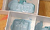
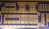
For some time I have been working on scratch building master styrene pieces to make molds from. The pieces of the master, when assembled, will make a Mi-Jack Translift crane in Z scale. It has taken a few months to get to this point, but I have good news. The masters are complete, the molds have been poured, and all that is left is to mix up some casting resin and fill the molds. The biggest part of this task is complete. Now I have two more items to create. The artwork for the etched brass details and the decal sheet. The artwork for the etched brass pieces is already made, I just need to adjust a few lines here and there and it will be ready to etch brass. The decals will only take an hour or so! Crossing my fingers, I might be finished with all of this by the end of this long weekend! Here are some photos of the mold process.
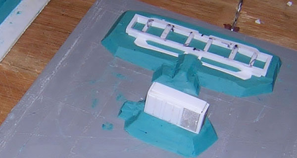
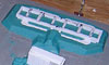
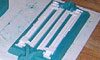
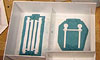
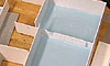
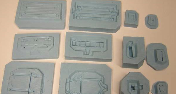
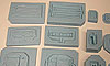
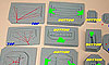
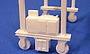
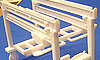
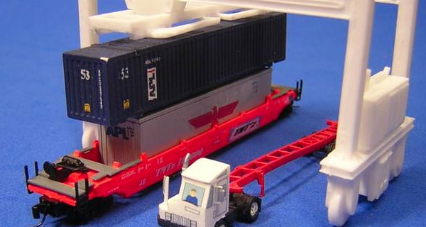
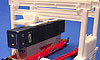
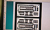
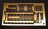
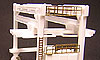
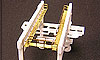
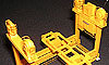
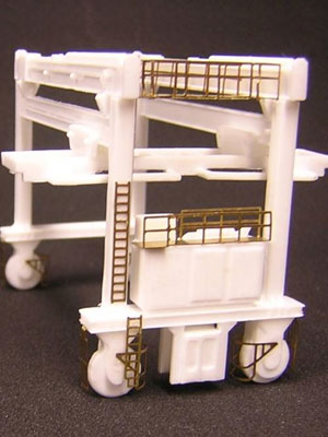
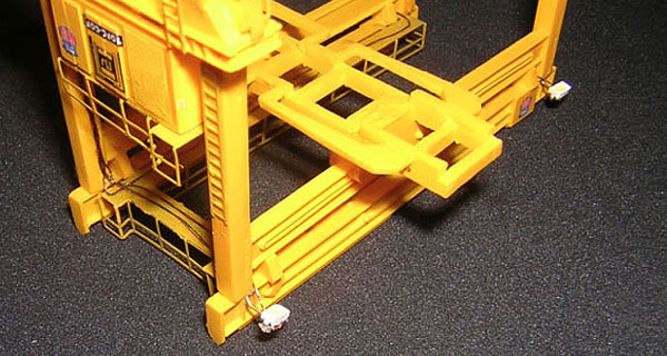
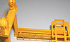
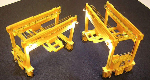
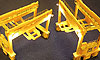
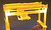
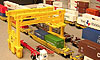
There they are! Ready to be filled with casting resin! On complex molds, I have learned to use many holes, plus to cut reservoirs connecting to the item I want to cast. The holes help to eliminate the bubbles, plus also supply that part of the mold with extra resin. I also strategically cut large reservoirs into the bottom mold to hold extra resin too. Reason for the reservoirs: I cut the reservoirs to hold extra resin. I place most of my molds into a 2 gallon pressure pot for one hour as soon as I pour the resin and close the mold. I then seal the lid on the pot and apply 25-40 psi of pressure. The pressure help eliminate any small bubbles that may be in the molds. Also, the pressure uses the resin, in the reservoirs, to fill the mold voids where the air bubbles were. The only thing that survives the pressure pot are large bubbles. I take care to eliminate all bubbles in my molds before I close them. Sometimes I miss a few, but the pressure pot eliminates most of them. Note the photo comparisons. The first is the actual photo of the molds and the second is the same but shows where all vent holes are and all reservoir areas. Holes in tops, reservoirs in the bottoms. Progress is so sweet! Above is the first copy of the Mi-Jack out of the molds. I cleaned the pieces up with a hobby knife only. Still some rough edges to sand/file off before any painting or gluing. Here are two photos with a MTL Husky and two hi-cube containers to show the height clearances. You can drive a train under them!
Hah! I swear, for me not being employed, it sure does feel like it. I am either casting resin in molds, cleaning and "resist"-ing sheets of brass, or creating etching artwork, or etching, or exposing resist to UV rays, or stripping, or painting, or decaling! Ugh!!!! This week I have done it all and it seems like I have done nothing! Double Ugh! OK, it is Friday morning at 1:12am and I have just finished etching the first brass fret for the Mi-Jacks. I only did one so far. Will do 7 more tomorrow (I mean today). More after that. I have assembled one completed Mi-Jack. Here it is! Here are a few photos showing the first Mi-Jack I am working on. I airbrushed it today and applied the decals. It is for a Union Pacific Yard and goes to Juerg in Switzerland. I still need to paint the wheels and a few details before I apply a dull clear coat. Tomorrow it will be complete!
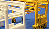
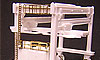
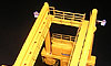
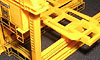
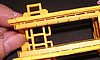
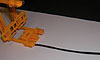
Today I bent the end of the brass rod about 1/8"" from the light and trimmed the brass past the bend about 1/16". I drilled a hole under the bottom of the drive wheel about 5/8" deep and centered. I drilled a slightly smaller hole diagonally near the motor housing on the inside to break thru to the larger hole in the wheel. This is where the wires will go to conceal them. I used the same drill bit to drill small short holes on all 4 outer corners of the main beams. The bit went diagonally into the vertical beam. Hole only about 1/16" deep. Photo below shows the vertical column and the motor housing. Notice the wire as it hugs the inside of the vertical column and disappears in the hole drilled into the drive wheel. I then routed the wires from each corner of the Mi-Jacks main horizontal beams. I glued the end of the bent brass rod, attached to the LEDs, into each of the 4 holes drilled. I adjusted the LEDs so they would shine downward and slightly inward. I let the glue dry. I then routed each wire along the bottom of the walkways, super gluing as I went. All of the wires converged at the vertical column where I drilled the hole thru the drive wheel. Once all 8 wires met at the column, and the glue dried to hold them in place, I carefully twisted all 8 wires for about 4 inches. I placed the straight twist of wires against the vertical column and thru the holes I drilled thru the wheel. The wires now stick out of the bottom of the wheel. I glued the wire twist to the vertical column.
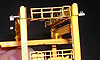
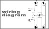
Photos show wires converging at drive column and twist along that column. Wires are glued to the bottom of the walkway. The wires were at various lengths about 8" long coming out of the bottom of the wheel. I then trimmed them all to about 6". I have not proceeded past this point yet. I plan on using a 9 volt battery to make the lights shine. I will be using two parallel series of two with a 100 ohm 1/8w nano resistor on each parallel connection. According to Ngineering mathematics, this is the correct method of choice for two 3.6 volt LEDs in series. Please correct me if I am wrong. A hole will be drilled thru the layout/module and the wires past thru the hole and connected to the power source on the bottom. All wires are hidden under the walkways and thru the wheel. Only place you can see the wiring is on the motor housing side of the vertical column, drive wheel corner. Photo below shows the under side of the walkways and the column that the twisted wires are following. Shows the angle of the LEDs too All wiring, brass rod, glue and any other nonpainted surfaces will be painted the same yellow as the Mi-Jack and finally, I can paint the black details, flat clear coat it, and it will be finished!
I have finished the electronics and electrical installations. I have mounted a 100 ohm 1/8w nano resistor to the underside of the walkway and soldered the positive leads to it. One resistor on each side. Remember, I have two parallel, series circuits. 3.6v + 3.6 v = 7.2v required to light up the LEDs for one set of series. Parallel the two series together and there you have it! Finished! Calculations say use a 100 ohm resistor in this series, so that is what I did. I used a small diameter piece of shrink tubing to protect the wiring coming out of the bottom of the wheel. I then heated the tube at the wheel working it small enough to fit inside the drilled hole. I then glued the tube into the wheel using E6000 glue. Source of materials: Ngineering www.ngineering.com 2x3 Super White LEDs #N1021-2 2/$7.50 2x3 Super White LEDs #N1021-10 10/$35.00 #38 Magnet Wire #N5038 $4.95 100 ohm 1/8w SMD Resistor #NA1000 20/$1.65 12w Mini Soldering Iron #N40MZ $25.95 Needle Tip for Soldering Iron #N4081 $6.25 Low Temp, Silver Bearing Solder #N4200 $1.95 Electronic Goldmine www.goldmine-elec.com Brilliant White Deluxe SMD LED #G16010 $.89 each 100 ohm SMD Resistor #G234R 20/$1.00 Radio Shack 15w Soldering Iron #64-2051 $7.99 .015 dia., 1oz, Silver Bearing Solder #64-035 $3.99 |

 |
© 2009 - 2010, Jürg Rüedi. All rights reserved